Cache Hierarchies and Coherence: A Security Researcher's Perspective

This post is an advanced overview of how CPU caches and the memory hierarchy works and how they are relevant from a security research perspective. We will cover multiple topics from the ground up, including cache organization, associativity, coherence protocols, virtual memory translations, as well as how these things can be a potential attack surface for side-channel attacks and covert channels. A basic understanding of caching and computer organization is assumed.
The Memory Hierarchy
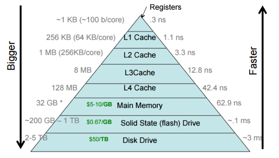
Computer memory is organized in a hierarchy consisting of multiple levels. The fastest memories are the on-chip register file, which provides fast latency to a number of data words. Main memory is organized as massive arrays of DRAM memory cells which are comprised of a capacitor and transistor to store a single bit of information.
The tradeoffs of main memory being implemented using DRAM cells and being physically distant from the processor leads to orders of magnitude of greater latency than accessing the on-chip register file. To bridge the gap, we add multiple levels of caches in between the register file and main memory to store frequently accessed data with a much lower latency than going directly to main memory.
Conceptually, every level in the memory hierarchy acts as a “cache” for the level above it. The last level cache (LLC) caches frequently used data from main memory. Main memory acts as a cache for memory pages in a swap space on disk. Beyond this, disk can act as a cache for data on a network. This organization allows frequently used data to be stored on a medium that minimizes the latency to access it, but we are limited by cost and storage space at each level in the hierarchy. When an access to a level results in a cache miss, meaning the data is not present, the access must go to the next level in the hierarchy and then be brought into the original cache level so that future accesses will result in hits and have lower latency. This brings us to the principle of locality
Locality of Reference
The locality priniciple is crucial in caches, and specifies that programs will typically access data and instructions that were recently used or are located nearby. There are two types of locality that are crucial to understanding the memory hierarchy.
Temporal locality specifies that data that was previously used will likely be used again in the near future. Hence, on a cache-miss, we bring the data into our cache so that future accesses to the same data will result in a cache hit.
Spatial locality specifies that data in close proximity to data that is being accessed is also likely to be accessed in the future. An array is an example of this, as it is organized contiguously in memory and an array access to one element likely means that the other elements will be accessed in the near future as well. Because of this principle, caches are organized into cache lines of a fixed size so a single cache-miss will not only bring the accessed data into the cache, but a specified number of words surrounding it will also be brought into the cache so their accesses result in hits.
Cache Organization
Because of spatial locality, CPUs will fetch fixed-size chunks from memory known as blocks or cache lines. A typical cache line size is 64 bytes. In order to facilitate this, memory is organized into blocks and each cache line can store a block from memory. An access to a memory byte X will result in a block-aligned fetch of the block of memory that contains X.
When the CPU requests an address, it needs to know three things:
- Is the block already in the cache? (Cache hit or miss)
- If it is a hit, where in the cache is the block?
- If it is a hit, where in the block/line is the requested data?
These three questions are answered by the cache using a tag or block number. Typically, the requested address is divided into portions, one representing the tag and another representing a block offset to find the requested data word. Each cache line contains tag information specifying the block that is currently occupying that line, and a comparison between the tag of the request and the tag stored in the line(s) will determine whether an access is a cache hit or a miss. The number of bits allocated for the block offset/tag field of the address is $ log_2(m) $, where $m$ is the number of blocks, and the same goes for the block offset field, where $m$ is the number of bytes in a block. Here is how an address would be divided for a fully associative cache:
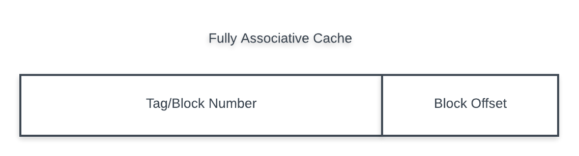
Here I use the terms “block number” and “tag” synonymously but that is not always the case. In set-associative caches, the block number is once again divided into two portions, one being the tag to compare against and the other being an index field to choose the cache set.
Associativity
As mentioned previously, caches can be set-associative and be organized into multiple sets which store a number of lines. Set-associative caches have benefits and tradeoffs when it comes to performance
Fully Associative
Previously, we have assumed a fully associative cache, in which each memory block can be placed in any line within the cache. There are no restrictions on which line can hold a specific block. These caches are typically small in capacity. Cache-hit time is affected since in order to determine whether an access is a cache hit, we must compare the tag of the address to the tags stored in every single line in the cache to see if any of them could be a hit, which is increases latency and power consumption. A fully-associative cache can be though of as an “N-way” set-associative cache, where the entire cache is considered as one giant set with N lines, where N is the number of lines in the cache.
Direct Mapped
A direct-mapped cache splits the block number portion of the address into a tag field and an index field, where the index field is of size $log_2(m)$ and $m$ is the number of lines in the cache. The remaining bits of the block number are allocated to the tag field. A direct-mapped cache is on the opposite end of the spectrum from a fully-associative cache, where each memory block can be placed in only one specific cache line. The cache line that it can be placed in is specified by the index field of the address:
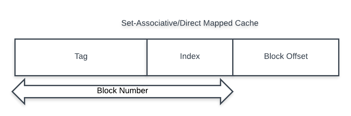
This reduces cache-hit time as there is only one line where a tag-check needs to be performed, but it comes at the tradeoff of more conflict misses as multiple blocks that map to the same line will cause collisions, evicting each other. In general, a lookup for this kind of cache involved determining the cache line to compare by checking the index bits, and then comparing the tag of the address against the tag stored for the cache line (assuming the cache line is also valid). If the tags match, there is a hit. Otherwise, there is a miss and we must fetch the data from the next cache level.
N-Way Set Associative
A middle ground between the aforementioned approaches is a set-associative cache. These caches are organized into sets, each set containing a number of lines, also known as “ways”. For example, a 4-way set associative cache would be a cache where each set consists of 4 cache lines. The address is divided the same way as a direct-mapped cache, except the index field is now calculated using the number of sets, rather than the number of total lines in the cache.
The advantages to set-associative caches is that tag checks no longer need to check all the cache lines (such as in a fully associative cache) nor are we limited by an increased conflict miss rate due to block collisions (such as a direct-mapped cache). Instead, a block that maps to a particular set can be stored in any of the ways of that set, and tag checks now only need to check all the lines belonging to that set rather than all the lines in the entire cache. Lookups happen similarly to a direct mapped cache, except that the index field will specify the set to check in the cache and a tag comparison is made against all ways in that set.
In addition to a tag, each line in a cache contains some additional bits. Primarily, a valid bit is present to identify whether a cache line is valid. If a tag matches but the line is invalid, the access should be treated as a miss. On a cold cache, the valid bits of all the lines are unset, and any cache accesses will result in a compulsory miss until the data is brought into the cache for the first time and the valid bit is set.
Misses and Replacement Policies
Cache misses can be broadly categorized into four distinct categories:
- Compulsory Misses: On a cold cache, all the lines are invalid. These misses are called compulsory because they are required to miss to bring the data into the cache for the very first time.
- Conflict Misses: These are misses that are a result of limited associativity in the cache, resulting in collision due to blocks mapping to the same line. Essentially, these are misses as a result of accesses that would be a hit in a fully-associative cache of the same size.
- Capacity Misses: These misses are a result of limited space in the cache, and occurs when the program’s working set is larger than the cache itself causing evictions of useful data to make room for new data.
- Coherence Misses: These misses are a result of coherence traffic. Lines can be invalidated due to another processor issuing a write to shared data, which results in a forced fetch from memory due to the cached copy being stale.
Coherence protocols are a bit complicated and will be discussed in a subsequent section.
On a conflict miss in a set-associative cache, we must determine which line in the set must be evicted and replaced. This decision is not trivial, and there are many options with varying tradeoffs, but a common method is LRU (least-recently used). This replacement policy chooses the least-recently used line in the set for eviction on a conflict miss to allow the more recently used lines to remain in the cache and continue to hit.
In order to implement LRU, each set in a M-way set-associative cache contains M LRU counters of size $log_2(M)$. The purpose of these counters is to keep track of which way in the set was least recently used. The most-recently used line in the set maintains the highest counter value, while the others are decremented accordingly. On eviction, the line with the counter value of 0 is selected as it is the LRU line.
The large problem with this is that we now have to maintain LRU counters for every line in the cache. Further, these counters need to be maintained to ensure consistency, and updated on every cache access regardless of whether it is a hit or a miss, which is bad for performance. As such, this method of using LRU counters is quite expensive and we are better off choosing a different policy that attempts to approximate LRU, such as NMRU (not most recently used).
Write and Write Miss Policy
Another important decision to make in the design of a cache is the write policy. In other words, what happens on a write miss. There are two primary questions that we want to answer:
- Do we insert blocks we write into the cache?
- Do we write to the cache or also write to main memory?
The former question can be determined by the chosen write-miss policy. A write-allocate policy will insert blocks written into the cache, as there is often times some locality between reads and writes. Data that is written will often times be read in the near future. A no-write-allocate policy will not bring written blocks back into the cache.
The latter question is answered by a write policy. A write-through cache will cause every write to a cache line to also synchronously write through to memory as well, whereas a write-back cache will only write to memory when data is evicted from the cache or when the cache is flushed. Write-back caches have many advantages in that memory traffic is minimized, but we must also keep track of which blocks have been written to and are “dirty” in order to ensure that only those blocks that have been modified get written back on replacement.
There is typically some association between these choices. A write-back cache usually implements a write-allocate policy and a write-through cache uses no-write-allocate, since writes need to be written to memory anyways.
Virtual Memory and Caches
This section will review the basics of virtual memory and explain more advanced cache considerations when it comes to virtual memory. The first half of this section is just a review of virtual memory which should be relatively familiar and will not be discussed in great detail.
Virtual memory is an abstraction on physical memory in order to facilitate multiple programs running on a system and provide each program with the illusion that it can access the entire address space provided by main memory. It provides each process with its own dedicated virtual address space in which it appears to have sole access to the virtual memory. In order to facilitate this, memory is divided into fixed size pages and a virtual address must be translated into a corresponding physical address which denotes the actual address in main memory where the data resides.
This way, multiple processes can share the same virtual address space and translate those addresses to different physical addresses in main memory.
Page Tables
The translation information between virtual pages and physical pages (also known as page frames is handled through structures known as page tables. Typically, each process has its own page table for the translation of its own virtual address space. The page tables themselves are stored in main memory.Each page table entry (PTE) stores the physical frame associated with the corresponding virtual page.
Similar to the caching examples, we must divide a virtual address into two components: a virtual page number (VPN) and a page offset field. Using the VPN we can index into the corresponding process’s page table to get the physical page number where that page resides, and the offset bits remain the same. A PTE can store the physical frame number or indicate that the frame exists on disk, in which case a page fault occurs and the corresponding page is loaded from a swap space on disk. In terms of the memory hierarchy, a page table here acts as a cache for page frames on disk and a page fault can be thought of as a cache miss.
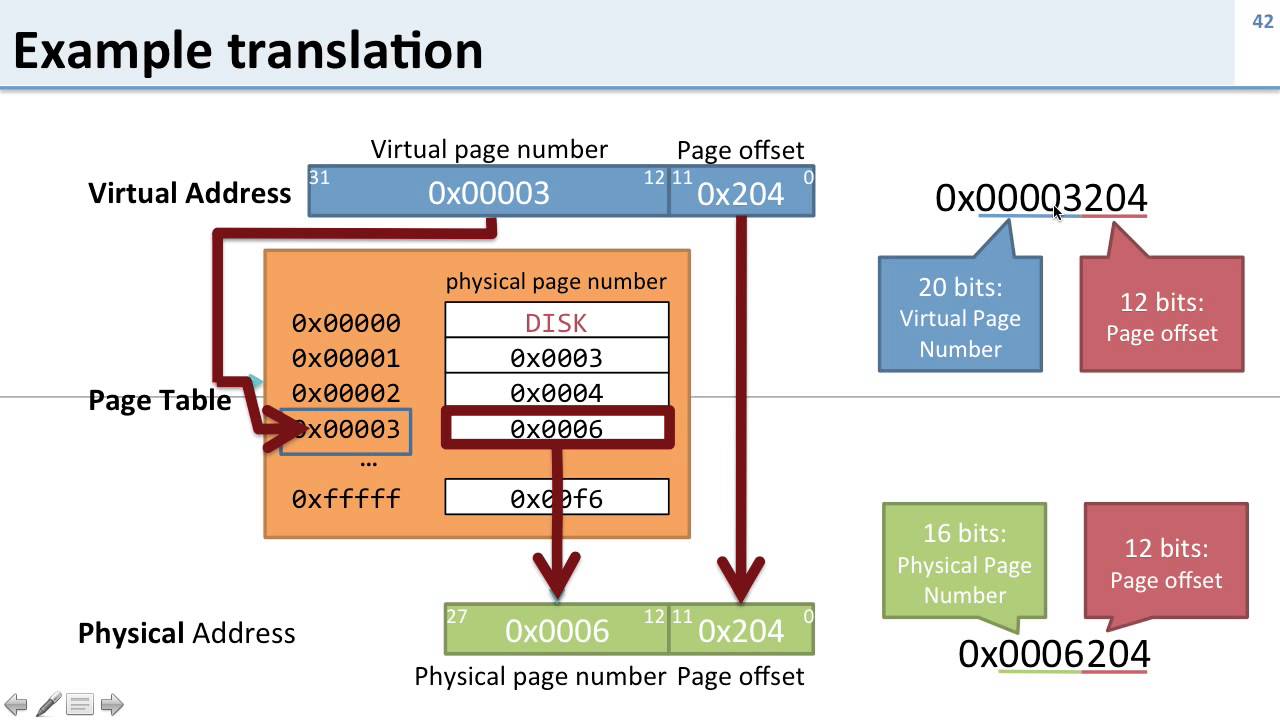
This works well, but can easily become a nuisance. In a single level page table, there must be a PTE for every possible VPN to PPN translation for the process, meaning that each page table for a process will be quite large. On a 32-bit system (assuming a 4 byte PTE and a 4kB page size), the page table ends up being around 4MB. If we have multiple processes running on the system, this effect is compounded since we now need seperate page tables for each process.
In order to fix this, we can apply our principles of caching and add yet another layer of indirection to form multilevel page tables. This way, we can actually page out page tables into disk. At most, we need at least one outer level page table to be memory resident so that we know where to access the inner page tables. The entries of this outer level page table now hold a pointer to the inner level page table it references, so we know whether it exists in memory or on disk. In order to facilitate this, the VPN field of the virtual address must be divided accordingly into sections depending on how many levels of page tables we are supporting.
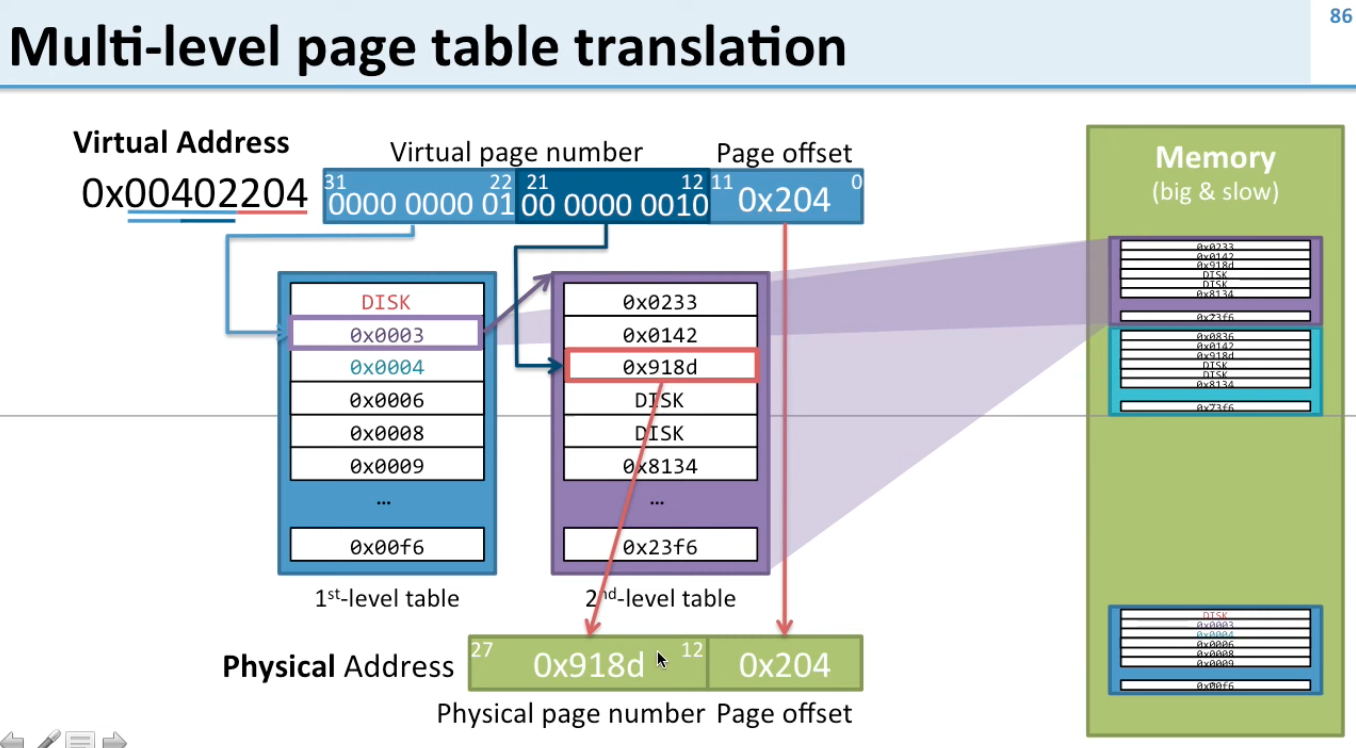
This has the added advantage of not needing a PTE for every virtual page translation. If there are large gaps in the address space that are unused by the program, then the outer level page table could simply indicate in the corresponding entry that the inner level page table for that region is unnecessary and does not need to be memory resident.
Translation Lookaside Buffers
Translation Lookaside Buffers, or TLBs, apply the principles of caching to virtual memory translations. Recall that in order to support virtual to physical translation, there must be at least one outer level page table that is memory resident. It turns out that we can cache these translations as well so that we don’t need to perform an expensive page table walk every time we want to get the final physical translation. Even if the individual page table entries are cached, there needs to be a cache access for every level of page table.
The TLB acts as a small and fast cache that is solely for virtual memory translations, and it only stores the final translation that you would get after walking through all the levels of the page table. All of our virtual memory translations would then go through the TLB, and only walk the page tables if we have a TLB miss, in which case the final translation would be put into the TLB. Typically, the TLB is a highly associative cache since they are small and require fast translation.
TLBs themselves can be organized into a hierarchy, with L1 being fully associative and larger L2 TLBs being set-associative
VIPT Caches
When discussing data cache and TLB considerations, we must consider whether the address translation/TLB access happens before the cache access or after. This is an important consideration to make, since a cache access’s latency could be affected by a TLB miss and access to main memory, and also has considerations to make regarding aliasing (When multiple virtual addresses map to the same physical address). Typically, there are three choices:
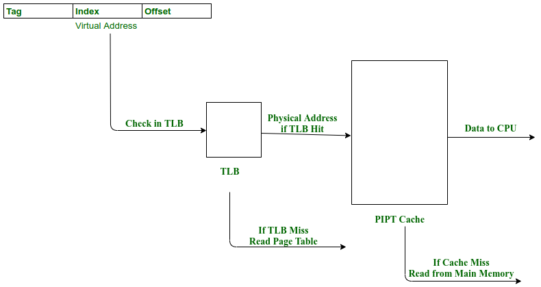
- Physically Indexed, Physically Tagged (PIPT): These caches use the physical address for both cache access and TLB access. The virtual address is sent to the TLB for a translation to a physical address. Then, this physical address is used to access the cache and a tag-check is performed to see if there is a cache hit
- This is slow due to address translation being required, but avoids aliasing problem
- This is slow due to address translation being required, but avoids aliasing problem
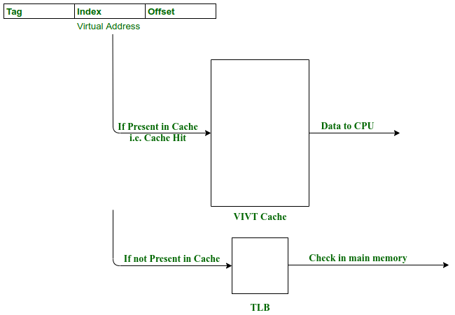
- Virtually Indexed, Virtually Tagged (VIVT): These caches use the virtual address for both cache access and TLB access. Since a translation is not necessary, both the TLB access and the cache access can happen in parallel using only the virtual address
- Suffers from aliasing problem, since several virtual addresses could be cached separately even though they refer to the same physical address
- Needs to flush the cache on a context switch since virtual address spaces of different processes cannot overlap.
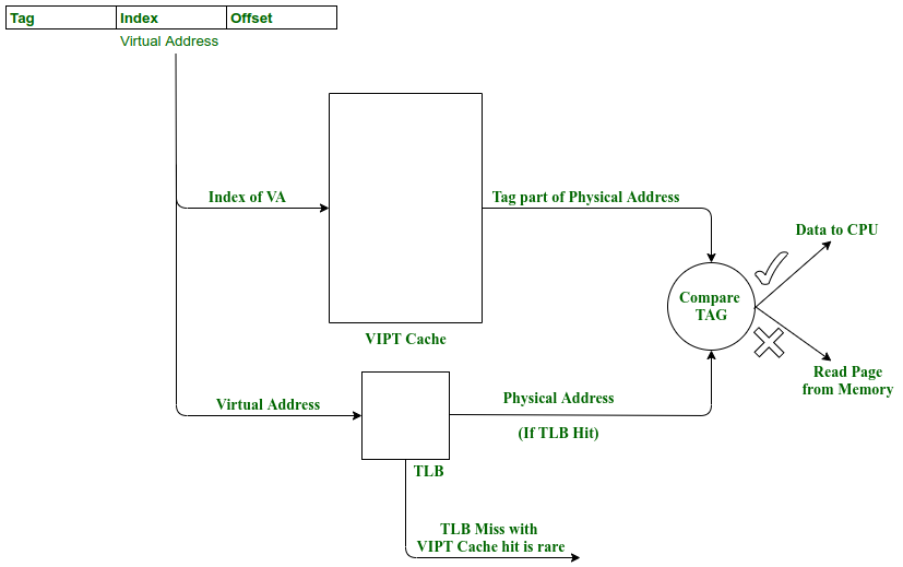
- Virtually Indexed, Physically Tagged (VIPT): Uses the virtual address to index into both the cache and TLB in parallel, but performs the tag check with the physical address from the TLB.
- There is no aliasing so long as all the index bits come from the page offset field of the address. This limitation means that the cache can be of a limited size.
- There is no aliasing so long as all the index bits come from the page offset field of the address. This limitation means that the cache can be of a limited size.
The VIPT cache seems to be the best of both worlds and avoid problems regarding aliasing if the cache is sized appropriately. There are some other considerations to make as well. If symmetric multithreading (SMT, or hyperthreading) is enabled, we would need a thread-aware TLB to know which thread a TLB entry maps to.
Advanced Cache Optimizations
In discussing cache optimizations, we are attempting to improve average memory access time (AMAT):
\[AMAT = Hit Time + Miss Rate * Miss Penalty\]We can improve any of these components, which will bring down overall AMAT.
Pipelined Caches
Adding a pipeline to cache accesses allows us to overlap one hit over another, thereby improving hit time. Various steps are involved in determining a cache hit:
- Indexing into the cache using the index bits and reading the tags of all the ways
- Comparing the tags for a match
- Adding the offset field to get the actual data out.
Each one of these could be a pipeline stage, thus allowing multiple cache accesses to be overlapped
Way Prediction
Way prediction is a method to reduce the slow hit time in a highly associative cache. When a cache set is determined, all ways in that set must be compared against the tag to determine if there is a hit, which increases hit time and power consumption. Instead, if we make a guess as to which line in the set is most likely to hit, we would initially check that line and only check the other ways if there is no hit with the initial check.
If our initial check was a correct guess, we would have similar performance to a direct mapped cache. If not, we will simply do a normal set-associative check against the other ways.
There are many methods to try to predict the way that is most likely to result in a hit, but this is beyond the scope of this post.
Prefetching
Prefetching is an optimization where we predict what blocks will likely be accessed soon and bring them into the cache ahead of time so that when they are accessed, it will result in a cache hit. We must be careful to prefetch within a proper time interval. If we prefetch too early before the speculative load, the prefetched data could potentially be evicted by other data brought into the cache.
If our prediction was correct, we eliminate a cache miss that would have happened without prefetching. However, if we were incorrect we suffer from cache pollution as we might have kicked out useful data to make room for our unused prefetched data.
Non-blocking Caches
Caches can be designed to be non-blocking, which allow for memory level parallelism. This allows things like hits from different data requests to be handled by the cache even when it is currently waiting for data from a previous cache miss, which improves performance since it doesn’t stall completely until the miss is resolved.
In order to facilitate this, a non-blocking cache can have Miss Status Handling Registers (MSHRs) which track pending memory requests. An MSHR is allocated when a data request comes in to see if there is already an outstanding miss that is currently occurring. If so, we have what is known as a half miss, at which point we add the instruction to the MSHR. If not, we know that this is a new miss, and we allocate an MSHR to track it. When the miss is complete, all the instructions that suffered a miss or a half miss and were added to the corresponding MSHR are woken up and provided with the data returned from memory.
When the miss is complete, we can release the MSHR so that it can be used by another miss. The total memory level parallelism that can be supported is the number of MSHRs that the cache has, as these are the number of distinct memory accesses that can be overlapped.
Coherence Protocols
Cache coherence protocols are important to maintain a consistent or coherent view of shared data in multicore systems. A definition of coherence includes the following aspects:
- Write Propagation: If any cache writes to a cache line, that must be propogated to other copies of the same line in other caches
- Transaction Serialization: Reads and writes to the same location must be seen by all processors in the same order.
Any read by a processor in a coherent system will read the most recent value that was written by any processor, or it will read the most up to date value from memory
Snoopy Protocols
Snoopy protocols ensure cache coherence by snooping reads and writes on a shared bus initiated by other processors and performing the appropriate action based on the snooped transaction. Two coherence protocols that can be supported by snooping are write-update and write-invalidate
Write-Update
A core that snoops a write from another processor to a cache line that it has in its own cache will update its cache with the snooped value. The processor that initiates the write will put the dirty value onto the bus to be written to memory, and all other processors will snoop that value and update their own caches accordingly.
If we use write-through caches, every write will need to go on the bus and write to memory, which will cause a bottleneck due to memory contention. Instead, if we use write-back caches with a dirty bit, the memory contention is minimized as writes will only go through to memory when data is evicted. In this case, we would need the cores to snoop reads as well as writes, since a processor could issue a read to a memory location that is dirty in another processors cache and stale in memory. The processor that holds the dirty copy must snoop that read and respond to the read request with the data and the requesting processor will be updated with the dirty value
Other cores will respond to snooped reads much faster than memory does, so the core that responds must prevent the request from going through to memory and instead respond with the data itself
Another optimization that can be done is to utilize a shared bit in the cache lines to determine whether a line is shared among cores or not. Previously, every write needs to go on the bus which causes bus contention, even when only one cache holds an exclusive copy. A seperate shared line is added to the bus and when a processor puts a read request onto the bus, it checks the shared line. If any processor snoops a read and determines that it has the same block within it’s cache, it will pull the line high. The requesting processor will now know whether the data it has is shared, and if it is not then all writes to that data can be done locally without generating any coherence traffic on the bus.
Write-Invalidate
More commonly we see write-invalidate protocols. These protocols simply invalidate local state copies of data when another processor writes to the same data, thus the next local access will result in a miss. The processor that has the dirty data will snoop that read and respond with the data using a cache-to-cache transfer
MSI Coherence Protocol
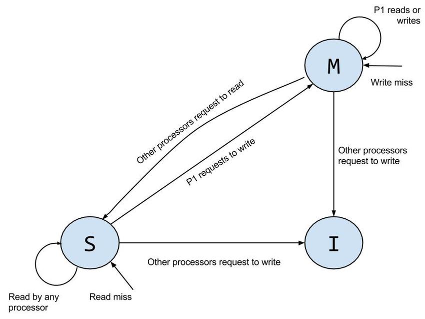
The MSI protocol is a write-invalidate protocol in which there are three coherence states that a cache line can exist in:
- Modified (M): The cache holds a dirty copy of the data. Only one core can exist in this coherence state at a time and hold the sole dirty copy of the data and other caches must be invalidated.
- Shared (S): The cache holds a shared copy of this line. This means another cache and this cache hold clean copies of the data to read from.
- Invalid (I): The cache line is invalid. This could be as a result of a bus upgrade in which another processor invalidated this core’s copy since it transitioned from the S to the M state, or we have a cold cache.
The Owned (O) State
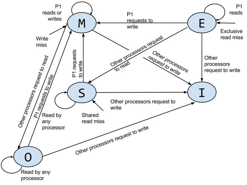
Other protocols based on MSI include an O, or Owned, state, such as MOSI. This state indicates that the line is dirty and that this core is the owner of the dirty line to provide to other cores during a cache-to-cache transfer. Previously, a line with the coherence state of M would transition to the S state when the respective core snoops a processor read, and that would also cause a flush to memory.
In this case, the processor would instead transition to the O state and no memory flush occurs, the processor in the O state would simply provide the data in a cache-to-cache transfer when it snoops a processor read. The data would only be written to memory when it is replaced. Essentially, the O state provides a dirty shared read access to the data where the core with the O state is responsible for updating memory, whereas the S state provides a clean shared read access to the data.
The Exclusive (E) State
Another addition to this protocol is the Exclusive, or E, state. This is present in protocols such as MESI or MOESI. A line transitions to the E state on a read miss and if there are no sharers to the data (i.e. the shared line is not pulled high by any other core). The benefit of this state is that if the core does a write, it can now directly transition into the M state without putting a BusUpgr signal onto the bus, needing to invalidate other copies, since it knows that it holds the sole exclusive copy. Essentially, the E state provides exclusive clean read/write access to the data.
Below is a state diagram for the MOESI protocol
Directory Based Coherence
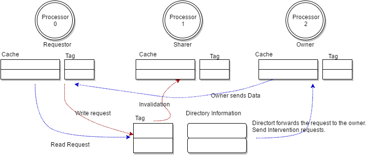
The bottleneck for the snoopy protocols is the shared bus as all coherence traffic must go through the same bus. Bus contention can increase as we have more cores sharing the same bus. Another protocol that attempts to solve this issue is a directory-based protocol, in which we rely on a directory that is distributed across cores and each directory slice serves a set of blocks. To facilitate this, we have a point-to-point network connection between the various cores so that requests can go between them.
A directory entry maintains the presence state of each cache block in the system and the directory will forward requests to the relevant nodes that have the data present in their caches. Directory-based coherence handles the coherence problem for NUMA systems. When we have multi core systems, often times we want to distribute the last level cache into multiple slices instead of having one big LLC. In this case, the home slice for a directory entry would be in that LLC slice.
False Sharing
A final point to mention is that invalidations due to bus upgrades can result in false sharing. Since invalidations occur for entire blocks/cache lines, it could be possible that two cores share a block but modify different data elements within that block. If one core modifies an element in the same cache line, it will invalidate the other core’s copy of that cache line even though it doesn’t touch the same data. Now when the other core goes to access its data it will incur a cache miss. This is known as false sharing.
Cache Attacks
Finally, I will briefly explore various forms of side-channel attacks that can be performed on caches. Cache attacks are a form of side channel attack that exploit timing variations of the memory system to leak data. From these attacks, we can determine based off of the latency of cache accesses whether a victim process has touched certain cache lines.
Flush + Reload
This attack relies on a CPU instruction to flush data from the cache. On x86, this is clflush. This attack requires that both the victim and the attacker shares data. To execute this, the following steps occur:
- Flush: The attacker flushes a shared memory variable X from the cache
- Victim runs: The victim process will begin execution and potentially access X. If it does, it will incur a miss and load it into the cache
- Reload: The attacker then reloads X and times the access. If the access is slow, then that means there is a miss and victim didn’t access X. If the access is fast, then there is a cache hit and the victim did access X.
On systems witout access to a flush instruction, this can be generalized to an Evict+Reload attack, where the first stage is any targeted eviction. Another generalization is the Evict+Time attack, where lines are evicted and instead the entire execution time of the victim process is measured to infer if the victim accessed the evicted data or not.
Prime + Probe
This attack involves the attacker filling (also known as priming) the cache with an “eviction set” and allowing the victim process to run and allowing the victim to evict lines it touches from the cache. Unlike Flush+Reload, this attack does not need shared memory. The general idea is:
- Prime: The attacker fills a chosen cache set with their own data and fills the set completely
- Victim runs: The victim begins execution and accesses memory mapping to the same cache set. In which case, it will incur conflict misses and begin evicting blocks that the attacker filled into the cache
- Probe: After the victim runs, the attacker reaccesses their data and measures access time as before to determine if the victim touched any lines and evicted them from the cache.
From this we learn which cache sets the victim accesses, when they accessed them, and how often.
ASLR Bypass Using AnC Attack (ASLR⊕Cache)
AnC is a microarchitectural side-channel attack that was demonstrated to break Address Space Layout Randomization (ASLR) by observing how the MMU interacts with the CPU cache hierarchy. It was discovered by the VUSec group at VU Amsterdam. This attack uses cache timing to leak information about page tables that the MMU touches when performing virtual to physical translations, allowing even untrusted JavaScript code to derandomize ASLR and discover heap pointers
The basic idea involves the use of caches to speed up page table walks. Since PTEs can be cached the attacker can measure cache latencies to infer which PTEs were accessed during a walk.
- Flush: The attacker flushes part of the LLC so relevant cache sets are cold
- Allow victim to access memory: This triggers a page table walk, bringing some entries into the cache.
- Time memory accesses: The attacker can now measure access times for cache lines and determine which ones were likely brought in by the page table walk. Thus, the attacker can now deduce which PTEs were used and reduce the entropy that ASLR relies on.
References
- https://www.geeksforgeeks.org/computer-organization-architecture/virtually-indexed-physically-tagged-vipt-cache/
- https://www.youtube.com/watch?v=Z4kSOv49GNc
- https://www.researchgate.net/publication/318860805_Obfuscating_Malware_through_Cache_Memory_Architecture_Features
- https://www.vusec.net/projects/anc/